PROJECT DESCRIPTION
The Pipeline Bridge Project included construction of a bridge to support new high-pressure gas pipelines located approximately 20 feet north of an existing, mostly at-grade pipeline alignment. The modular steel, truss-type bridge design includes a span of approximately 240 feet supported on two abutments and two interior columns. The project is set in the rugged Santa Susana Mountains — a geologically complex and seismically active area of California. This setting, spanning a steep, environmentally sensitive canyon, presented numerous challenges for SALEM Engineering Group, Inc.’s geotechnical investigation for the project.
Pre-investigation research had shown that the east, and likely also the west, bridge abutment and column supports were to be constructed within active landslides. The eastern landslide had moved as recently as 1994 during the Northridge Earthquake. The primary geotechnical challenge was to identify slide plane location/depth on both sides of the canyon and determine whether mitigation through landslide slope reconfiguration, tie-backs, pinning, etc. would be required, or if landslide loads could be mitigated, or overcome, through bridge support design.
SCOPE OF SERVICES
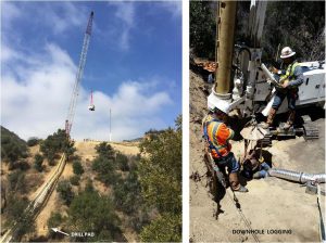
SALEM Engineering Group, Inc.’s fieldwork as part of the geotechnical engineering and geology investigation included five continuous core borings using a CME-type device, retrieving a total of 268 feet of 3.5-inch diameter core, and one 30-inch diameter 40-foot deep bucket auger borehole used for downhole logging. Subsurface investigation at the western bridge column required using a 350 ton, long-reach crane to lower both excavation equipment and a bucket auger drilling rig over 200 feet horizontally and over 100 feet vertically down the canyon wall to a small drilling pad cut into the steep slope. Fieldwork also included 2 days of geologic mapping to document the complex geology below the project site including two intersecting thrust faults, in addition to the landslide boundaries.
Geotechnical analysis included using weathered bedrock strength data, accounting for its variation with formation dip/direction, to conduct five slope stability sections under static and seismic conditions. Model strength data was modified slightly to allow the model to adequately mimic the locations of the major landslide slip planes identified during our subsurface investigation. Moment equilibria analysis and geometric methods were used to determine the lateral loads imposed by the landslide masses at abutments and columns, and several deep foundation configurations were assessed. Although still in the design phase, initial plans for deep foundations will likely include two 5-foot diameter CIDH piles below abutments and columns, strong enough to resist 200+ kip laterals loads and the potential loss of downslope lateral support in the event of a landslide. These deep foundations will be oriented perpendicular to the landslide movement direction to minimize lateral loads. Analysis also suggests these deep foundations, will the construction of additional rows of shear pins, will effectively locally pin the active landslides, limiting their potential for future movement.