
PROJECT NAME:
Lorena Heights Apartments
Los Angeles, California
SERVICES PROVIDED:
Geotechnical Engineering Investigation
Construction Inspection & Material Testing
PROJECT DESCRIPTION
The Lorena Heights Apartments Project consisted of the development of a multi-level apartment complex comprising of 112 two and three bedroom apartment units with large balconies, with a multi-subterranean parking garage and community center building. Unique challenges presented themselves during various phases of the development including various changes in project design, additional regulatory oversight (City of Los Angeles Department of Building and Safety [LADBS]), unexpected delays during construction associated with encountering contaminated soil
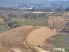
PROJECT BACKGROUND
Based on research by others conducted for a Phase I Environmental Site Assessment of the subject property, a church was moved to the project location in 1942 and approximately 60-foot high slope was laterally extended with soil from undocumented sources. At the request of the client and LADBS, SALEM Engineering Group, Inc. conducted an additional geotechnical study to assess the extent and depth of this undocumented fill. Elevated concentrations of total lead and other metals were found throughout the fill on the slope face. The depth of the proposed construction excavation on the eastern portion of the site was approximately 18 feet below the original grade level. On the western slope face where the contaminated fill soil was present, the maximum excavation depth was approximately 52 feet below grade. This resulted in the export of approximately 104,000 cubic yards of soil from the Site in preparation for construction. Some of the soil was contaminated with lead and had to be handled as a special waste.
SCOPE SERVICES
SALEM Engineering Group, Inc. completed a Preliminary Geotechnical Engineering Investigation for the proposed project in 2007. The initial project design incorporated standard soldier pile retaining walls. SALEM Engineering Group, Inc.’s geotechnical report included recommendations for slab-on-grade construction, over-excavation and re-compaction of 3 feet of soil below footing and slab (excluding removal of up to 25 feet of undocumented fill at the slope face), lateral pressures and seismic loading for foundations and retaining walls, and bearing capacity (dead + live loads). This original report was reviewed and approved by the LADBS, but the project was later put on hold.
Upon project reactivation, SALEM Engineering Group, Inc. was informed that major aspects of the project design had changed. Due to the integration of a 55-foot tall soil-nail wall into the design of the project, LADBS noted that SALEM Engineering Group, Inc.’s original report did not address engineering recommendations for construction of a soil-nail wall in addition to the originally proposed soldier pile retaining walls. LADBS exercised caution and scrutiny regarding design approval due to the fact that the reviewers had only approved two projects with soil-nail walls in the past decade — neither of the previously-approved soil-nail walls were proposed to be as tall (55 feet) as the soil-nail wall proposed for this project. SALEM Engineering Group, Inc. conducted additional field exploration and laboratory testing at the request of LADBS from which additional recommendations, analyses, and calculations for the proposed soil-nail wall were produced.
Consequently, SALEM Engineering Group, Inc. devoted more than 100 hours of Geotechnical Engineer and Engineering Geologist time to making the appropriate recommendations, analyses, and calculations to incorporate engineering recommendations for a soil-nail wall and wall monitoring system. Recommendations included specifics on tie-back design including ultimate bond stress, tie back angles, tie-back test frequency, loading and durations, and soil properties used to model the system of soil nails. SALEM Engineering Group, Inc. calculated the allowable deflection at tops of walls (0.75 inches for the 55-foot tall wall) and the width of the deflection influence zone (70 feet), and surcharge effects on the walls from adjacent structures. SALEM Engineering Group, Inc. also designed the wall monitoring system. The monitoring system includes four 70-feet deep inclinometers, six strain gauges mounted within the retained soil mass and six load cells mounted at the wall face.
SALEM Engineering Group, Inc. drilled three additional geotechnical soil borings at the site and conducted geotechnical laboratory testing on a select set of samples. The additional borings were drilled to provide supplemental subsurface data, including soil types and strengths behind the proposed soil nail wall to substantiate selection of soil properties for wall design.
During the soil nail wall design phase, SALEM Engineering Group, Inc. prepared design cross sections showing the site geology and wall and nail placement; determined inclinometer, strain gauge and load cell monitoring locations; determined soil parameters for tie-back and surcharge calculations; tie-back test frequency, loading and durations; determined appropriate seismic parameters for retaining walls; conducted slope stability analyses; and conducted wall deflection analysis. In addition to our initial 2007 geotechnical engineering investigation report, SALEM Engineering Group, Inc. prepared and submitted four additional reports or addendums to address issues associated with the soil nail wall design change, and attended several meetings with the design team and the LADBS. Throughout this process, SALEM Engineering Group, Inc. was in constant communication with all members of the design team to ensure efficient response to requests from regulatory agencies and to address design changes necessitated by unforeseen site conditions.
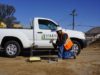
As the Soils Engineer of Record for the site, SALEM Engineering Group, Inc. designed the wall monitoring system. SALEM Engineering Group, Inc. directed the installation and monitoring of inclinometers, strain gauges, and load cells to assess movement of the soil-nail wall. An initial baseline reading was taken after completion of inclinometer installation and before soil nail wall construction. Weekly readings were conducted throughout construction, and bi-monthly to monthly readings were performed for 6 to 12 months after completion of soil-nail wall construction.
SALEM Engineering Group, Inc. also provided construction inspection and material testing services for this project, including soil compaction testing and earthwork observation, concrete inspections and sampling, and reinforced concrete inspections.
Related Services
Geotechnical Engineering
SALEM Engineering Group, Inc. offers a wide range of geotechnical …
Construction Inspection & Material Testing
SALEM Engineering Group, Inc. offers an extensive array of construction …

Structural Engineering
“Our Structural Engineering staff takes pride in providing …

Civil Engineering Design & Land Surveying
SALEM Engineering Group, Inc. has proudly developed a client …